Installing Wireless Equipment
The wireless equipment is delivered with a set of
fasteners.
Installing Network Adapters
You can install a network adapter on a desk top
or office partition, wall or ceiling. You will need to leave at least 5 cm (2
inches) free space on the sides and back of the device for ventilation. The
network adapters are generally delivered with factory-installed antennas.
Installing Access Points
We recommend that you install access points used
within a room on the wall (below the ceiling) or on the ceiling to provide the
maximum operating radius. Access points intended for use outdoors should be
installed according to the instructions for wireless bridges provided below.
The access points are generally delivered with factory-installed antennas.
Installing Wireless Bridges
Installing an Antenna. The antenna
is the most critical part of the wireless bridge. Antennas for wireless
bridges are generally installed on exterior walls or roofs of buildings using
tripod mounts, stanchions, or masts. The antenna must be reliably secured to
the structure supporting it in order to withstand loads from precipitation and
winds. The use of antennas with solid reflectors is not recommended in areas
with high winds; grid type antennas should be used in such cases.
Connecting an Antenna. Connect an
outdoor antenna to the connector according to the manufacturer�s instructions.
The shorter the connection between the wireless device and the antenna, the
lower the signal losses and the greater the range of communications, so the
wireless device should be installed as close as possible to the antenna. A
short flexible coax cable or semirigid feeder should be used to connect the
device to the antenna. The connection should not be more than 300 millimeters
(12 inches) long. The material and design of the connecting cable and
connectors should ensure adequate communications conditions at the operating
frequency. Of course, wireless devices with built-in antennas do not require
connection of the antenna.
Installation Location and Height.
Choose the antenna installation location and height so that you have a line of
sight to the opposite end of the wireless bridge. Read the antenna
manufacturer�s instructions, study the antenna pattern, project it onto the
terrain profile and geometrically determine the heights at which the antennas
at both ends of the bridge must be installed so that their patterns have a
line of sight. Obstacles such as buildings, structures, trees, and other
objects must not obstruct the line of sight. Optical instruments such as
theodolites, telescopes, or binoculars are generally used to verify the line
of sight between the antennas. However, a line of sight is not enough to
guarantee good communications. The fact is that radio signals propagate as
waves, rather than on a straight line. Therefore, even if we can see the
opposite end of the wireless bridge, this doesn�t mean that the radio signal
transmitted from one end of the bridge will reach the other end directly like
a laser beam. If there are obstacles near the path of the radio signal, then
reflection and/or absorption of the radio waves by these obstacles may lead to
phase distortions and attenuation of the radio signal, and thus to a decrease
in the data transmission speed. Therefore, the spread of the radio beam in
space must be considered when selecting the antenna installation height. For
this, you need to calculate the so-called Fresnel zone, specifically the
diameter or radius of the cross section of the radio beam at a given distance
from the antenna. The dimensions of the first Fresnel zone�the widest point of
the zone located at the midpoint of the link�can be calculated using one the
formulae below.
The formula for determining the radius of the
widest point of the Fresnel zone (in meters):
where Rm is the radius (in мeters) off of the
center line of the link, D is the distance (in kilometers) between the
antennas, and F is the operating frequency (GHz).
The formula for determining the radius of the
widest point of the Fresnel zone (in feet):
where Rf is the radius (in feet) off of the
center line of the link, D is the distance (in miles) between the antennas,
and F is the operating frequency (GHz).
For normal operation of high-quality
communications, the first Fresnel zone must be free of obstacles for at least
0.707 of the theoretically calculated zone. For example, for a wireless bridge
span 5 kilometers (3 miles) long, for 2.4 GHz band frequencies the radius of
the first Fresnel zone at the midpoint of the span (1/2 of the span) will be
approximately 12 meters (40 feet). This means that the line of sight must pass
8.5 meters (28 feet) above any obstacle on the beam path. Needless to say, if
an obstacle is located to the side of the path (for example, where the beam
travels between two buildings), the requirement is the same.
Grounding. The antenna must be
grounded according to the manufacturer�s instructions.
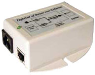
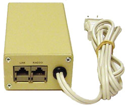
Connecting Wireless Equipment
The wireless equipment set includes an external
power supply with an integrated Power-over-Ethernet (PoE) adapter (the two
models are shown below).
All power supply units perform reliably in
outdoor applications due to their weatherproof housing rated for operation at
�10� C (14�
F) to +40� C (104�
F) and up to 90% relative humidity. The power supplies can be installed
vertically or horizontally on a flat surface, or fastened to a mast or
stanchion, or to the housing of the wireless communications device.
The power supplies are equipped with lightning protection. The built-in PoE
adapter is used to connect the wireless communications device to the power
supply and, where necessary, to a computer or other hardware. Straight-through
and cross-over twisted-pair cable of Category 5 or higher with RJ45 connectors
is used to connect the wireless devices.
|
IMPORTANT! Before connecting the power
supply to the electrical circuit, make sure that the voltage indicated on the
power supply housing corresponds to the voltage in the circuit used. Use a
voltage converter if necessary. The use of a power supply not rated for the
voltage in your circuit may cause short circuiting and damage to the power
supply and the wireless communication device connected to it.
The plug on the power supply cable is designed to be connected to the standard
outlets used in the USA. You will need a plug adapter (not included) to use
the power supply outside the United States.
|
Connecting network adapters. Connect
one end of the straight-through Ethernet cable to the connector on the housing
of the network adapter, and insert the other end in the PoE adapter socket
marked �RADIO� (or �AP�). You will need a cross-over Ethernet cable to connect
the network adapter to hardware (computer, server, printer, scanner, etc.).
Connect one end to the PoE adapter socket marked �LAN�, and the other to the
RJ45 port on the hardware. Plug the power supply into the outlet.
Connecting access points. Connect
one end of the straight-through Ethernet cable to the connector on the access
points, and insert the other end into the PoE adapter socket marked �RADIO�
(or �AP�). If you are using the access point to connect wired network
equipment (a router or hub, for example), use a second straight-through
Ethernet cable and connect one end to the PoE adapter socket marked �LAN� and
the other to the RJ45 port on the hardware. If you are connecting an access
point to a network server, you will need a cross-over Ethernet cable. Connect
one end to the PoE adapter socket marked �LAN�, and the other to the RJ45 port
on the server. (Skip this step if you are using the access point as a wireless
hub/router, i.e., without connecting it to the network equipment.) Plug the
power supply into the outlet.
Connecting wireless bridges. Connect
one end of the straight-through Ethernet cable to the connector on the
wireless communications device, and insert the other end into the PoE adapter
socket marked �RADIO� (or �AP�). To connect a bridge to network equipment (to
a hub or router, for example), use a second straight-through Ethernet cable.
Connect one end to the PoE adapter socket marked �LAN�, and the other to the
RJ45 port on the hardware. If you are connecting two wireless devices directly
for use in repeater mode, use a cross-over Ethernet cable. You will need a
crimping tool to connect the network cables to the waterproof connectors on
the bridge housing. Plug the power supply into the outlet.
Wireless Equipment Settings
You can select the settings for the wireless
equipment for operation in the network using any Web browser.
To access the administrative control panel for
the wireless device, you need to open your browser and enter the default IP
address of the wireless device you want to select the settings for in the
default address line (the default IP is generally 192.168.1.1 or
192.168.1.100). In the login window that opens, you will be prompted to enter
your username and password. Use the word admin (lowercase characters)
as your username. You can leave the password field blank, or enter the word
public.
Using the Web-based utility program, you can
-
View and change the current settings for the
device.
-
View statistics on communications speed,
communications quality, communications channels used, information on other
hardware in the network, etc.
-
Change the mode for communications with other
hardware in the network (ad hoc or infrastructure).
-
Change the function of the device (Access Point,
Access Point Client, or Wireless Bridge).
-
Change the settings to operate as a router.
-
Change the IP address for the device, Subnet
Mask, Default Gateway, and DHCP.
-
Choose the firewall settings to protect the
network against intruders.
-
Choose the settings for network security using
the Wired Equivalent Privacy (WEP) encryption standard.
-
Change the password for access to the utility
program.
-
Save and upload various settings.
-
Perform other operations for setting and control
of the device.
Operating Wireless Equipment
The operating conditions for your wireless
equipment must meet the following requirements:
Electric power. The electric power
must match the parameters indicated on the power supply or in the
specifications for the given device. An uninterruptible power supply should be
used where necessary.
Grounding. If your wireless device
has a built-in power supply, you should ground it by connecting it to a
3-prong grounded outlet or by directly grounding the housing. Housings of
wireless devices designed for outdoor installation and the antennas connected
to them must always be grounded.
|
IMPORTANT! DO NOT use the neutral wire for
grounding! Use the separate ground wire!
|
Storage and operating temperature.
The ambient temperature inside and in direct proximity to the device must not
exceed the storage and operating temperatures indicated in the equipment
specifications.
Humidity. The humidity inside and in
direct proximity to the device must be between 10% and 90%, and condensation
must not form.
Servicing Wireless Equipment
To ensure long, trouble-free operation, we
recommend that you inspect the equipment at least once per year to find
factors that might reduce the capacity of the equipment or cause it to fail.
If you are operating the equipment in a very polluted environment, you should
periodically clean off the dust, grime and other matter than might cause
corrosion of the wireless devices (housing, antenna and connecting cables).
You may void the warranty on the equipment if you
do not fulfill these requirements.
More information: